Crystal
- 1. Introduction
- 2. Video Menu
- 3. Video
- 4. Motor Positions
- 5. Crystal Rotation
- 6. Crystal Translation
- 7. Crystal Centering
1. Introduction
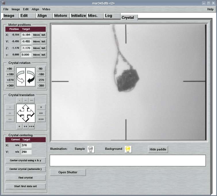
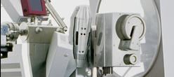
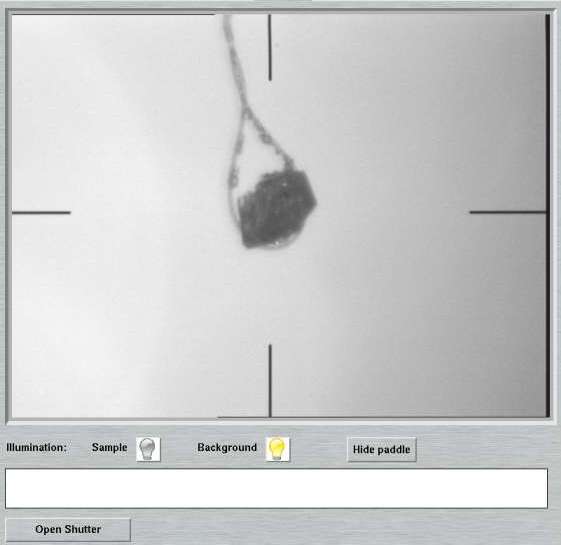
The "Crystal"-page can be accessed by selecting the corresponding tab in the main window or by pressing the "Ctrl+9"-key while the pointer is in the main window. Here, you can display a crystal as seen by the built-in video camera. The crystal can be repositioned and automatically centered.
The "Crystal"-page features several work areas:
- a menu bar with various options(see 2.)
- an area containing the frame grabber outut (video)(see 3.)
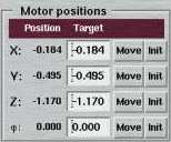
- an area for moving xyz-translations and PHI(see 4.)
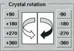
- an area for turning the crystal (PHI rotation) (see 5.)
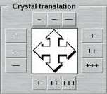
- an area for intuitive xyz-translations (see 6.)
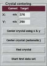
- an area for centering the crystal (see 7.)
2. Video Menu
The "Video"-menu pops up if the "Video"-button in the menu bar is pressed or if "Alt+v" is pressed while the pointer is in the main window. This menu allows for accessing different options that have to do with video. The choices are:
| Menu | Menu Choice | Shortcut | Description |
|---|---|---|---|

| TV window | Alt+t | Displays the video output in a separate window. This is sometimes necessary in order to watch the sample while moving a motor from within another page. |
| Show crosshair | Ctrl+h | Displays a digital cross-hair on top of the video layer with coordinates and units taken from configuration file | |
| Show crystal center | Ctrl+x | Displays a digital cross on top of the video layer at the x,y-coordinates that define the center of the sample | |
| Zoom x 1 | Alt+1 | Displays video at 1:1 magnification ratio | |
| Zoom x 1/2 | Alt+2 | Displays video at 1:2 magnification ratio | |
| Zoom x 1.5 | Alt+3 | Displays video at 1.5:1 magnification ratio | |
| Zoom x 2 | Alt+4 | Displays video at 2:1 magnification ratio | |
| Save Photo | Alt+p | Stores a snapshot in the directory where the program has been started. Output file name is "dtb-XXX.jpg" where XXX stands for a time description string. | |
| Save Empty Photo | Stores a snapshot as $MARLOGDIR/xtal/empty.jpg It is very important that this photo does NOT contain any pin or crystal feature. It must be an empty background image. Otherwise, automatic crystal centering is going to fail! Normally, it is not required to do this explicitely, since the program automatically updates empty images every time a sample is mounted. |
NOTE:
As by February 2004, XFree86 (versions 4.3 or smaller) has some serious bugs
in the libXv libraries having to do with video output.
One of the consequences is,
that depending on hardware, the overlay of digital cross-hairs or other digital
marks on top of the video output may not become visible. Another reproducible
bug is that zooming to magnification ratios > 1 does not work properly.
The code of program mar345dtb currently ignores these bugs and has
implemented some functions as if those bugs didn't exist. A future XFree
implementation may fix those bugs.
As by April 2009, the libXv libraries may not work at all as specified, depending on the video card and possibly main board drivers. As a consequence, the native model of XFree/Xorg to display video streams cannot be used at all. It is known that the propietary ATI/AMD video card drivers do not support this model, so none of the ATI cards can be used any more for displaying the built-in video stream. In order to compensate for these limitations, program mar345dtb can be configured to start an external TV-grabber program and "hijack" the window and make it appear to be a built-in screen. Effectively, our choice is a slightly modified version of program tvtime, which is a public TV viewing program. The modified version is called martv and mainly contains possibilities to display a cross-hair and to exchange information with program mar345dtb, in particular for centering issues. Please see chapter Configuration File in section Input) for more details.
3. Video
The video area becomes available on the "Crystal"-page depending on settings in the configuration file (see chapter Configuration File in section Input). This is the place where the output of a frame grabber device is displayed. Brightness and contrast can be altered directly using the slider bars underneath the video window. All other (less variable) settings have to be done from within the configuration file. Please note, that a frame grabber allows exclusive access to only one process. If the "Crystal"-page is up, the program tries to access the frame grabber but if another page is up, then the frame grabber is released and other applications may access the frame grabber.
Within the video area, the mouse buttons have the following functions:
- Left hand button: update xy-coordinates in the "Crystal Centering"-area
- Middle button: display current xy-coordinates in the upper left corner of the video area
- Right hand button: update xy-coordinates in the "Crystal Centering"-area
Note, that xy-coordinates have their origin in the upper left corner of the video area.
4. Motor Positions
In this area, motors that have to do with the sample positions can be displayed, moved or initialized. The motors are the xyz-translations of the goniometer head and the PHI-axis.
5. Crystal Rotation
In this area, the motor that has to do with the sample rotation (i.e. the PHI-axis) can be moved by 90, 180, 270 or 360 degrees by only pushing the corresponding button.
6. Crystal Translation
In this area, the motors that has to do with the sample xyz-translation can be moved. There are 3 choices for the amount of displacement: a large one, a medium one and a short one for fine-tuning. While the upper or the lower buttons will always move the z-translation (either in positive or negative direction), the buttons on the left hand side and the ones on the right hand side move the x or the y-motor in the goniometer head, depending on the current PHI-position. The indicated directions correspond to what will be observed in the video area.
7. Crystal Centering
This area can be used to reposition a sample, e.g. for centering it with respect to the cross-hair. The xy-coordinates in the upper section correspond to the coordinates of a point in the video area, the origin being the upper left corner. The default center will be taken from the configuration file. A user has 3 choices to update the x and y coordinates:
- Enter desired values manually in the corresponding fields for x and y
- Click the left or right hand side mouse button at the desired position of the video area (see above).
- Let external crystal localization software find xy-coordinates
The push-buttons in this area have the following functions:
| Button | Description |
|---|---|
| Center crystal using x and y | The "target" xy-coordinates are translated into a suitable motion of the xyz-translation motors. |
| Center crystal (automatic) | Automatically center the crystal. The method is described in more detail in the chapter Center crystal (automatic) |
| Find crystal | Automatically locate the crystal. The method is described in more detail in the chapter Find crystal |
7.1 Find crystal
Automatic crystal finding consists of the following sequence of steps:
- Shoot a photo and locate crystal in photo, i.e. determine xyz-coordinates of the presumed center of the crystal.
- Drive goniometer head xyz-translations according to the result of the previous step.
The crystal localization relies on an external program and the command to use
within program mar345dtb can be specified in the configuration file.
It defaults to "loopfind" and it gets 3 arguments:
- $MARLOGDIR/xtal/find.jpg (or some other arbitrary name)
- $MARLOGDIR/xtal/empty.jpg
- $MARLOGDIR/xtal/xhair.jpg
The first file is supposed to contain some sample. The second file may not contain any sample, i.e. it must be empty and contain only background. The sample finding algorithm depends on such a background file. Since illumination may vary depending on environmental conditions, the "empty" file is updated each time a sample is mounted. The third file is produced automatically out of the "empty" image and extracts the fixed cross-hair artefacts in the image. This is technically necessary and is used as a mask to leave out invalid pixels in a photo.
The program loopfind is implemented as a very simple shell script that passes values to a program called marloop that actually does the job of locating the crystal. This program has several possible exit conditions:
- The sample is located and the program prints x and y coordinates.
- The photo is empty, i.e. it doesn't contain any significant structure. This means, that if there is a pin with a loop at all, it is completely outside the viewing range of the camera. Typically, this means that the pin is way too short or too much tilted. If it is too short, the only reasonable action is to drive the z-translation.
- The photo contains a large area - supposedly the pin - but no loop. This implies that the sample has to be moved along z towards smaller values. Please note, that in the current implementation the algorithm may take somewhat long (up to 2 minutes on a 2 GHz processor) to identify this situation.
Within the "Find crystal-procedure only the first case is going to automatically produce an action, i.e. xyz-motors are driven according to the obtained xy-coordinates of the sample center.
The progress of the computations and final results will be printed in the white area underneath the contrast slider.
7.2 Center crystal (automatic)
Automatic crystal centering is a complex procedure consisting of a series of steps. The program mar345dtb implements 3 methods for automatic centering.
The first method (i.e. CSC METHOD 0 in the configuration file) comprises the following sequence of steps:
- Mount crystal (when chosen as an option of a data collection)
- Shoot a photo and locate crystal in the photo, i.e. determine xyz-coordinates of the presumed center of the crystal.
- Drive goniometer head xyz-translations according to the result of the previous step.
- Drive PHI by a predefined value and repeat the previous two steps
- Repeat the previous 2 steps for a predefined number of photos
The number of photos and also the phi rotation inbetween the photos is freely configurable. Typically, 4 photos at intervals of 90 degrees in PHI give good results. Also the starting value is configurable (typically at PHI=0). The entire procedure may be repeated over several cycles, but typically 1 cycle of operations should be enough.
The second method (i.e. CSC METHOD 1 in the configuration file) comprises the following sequence of steps:
- Mount crystal (when chosen as an option of a data collection)
- Shoot a series of photos at predefined PHI intervals
- After shooting the last photo, determine xyz-coordinates of the presumed center of the crystal by analysing all photos in single step.
- Drive goniometer head xyz-translations according to the result of the previous step.
The number of photos and also the phi rotation inbetween the photos is freely configurable. Typically, 9 photos at intervals of 40 degrees in PHI give good results. Also the starting value is configurable (typically at PHI=0). The entire procedure may be repeated over several cycles, but typically 1 cycle of operations should be enough.
The third method (i.e. CSC METHOD 2 in the configuration file) is similar to method 0, in the sense that each photo is evaluated individually. The difference is that there is an additional parameter that comes into play which is a certain tolerance of movements inbetween two successive PHI movements. If the crystal movement drops below that configurable threshold (e.g. CSC METHOD 2 TOLERANCE 0.2 ) then the centering may be considered as successful. However 4 photos 90 deg. apart will always be shot. If the computed shifts exceed the tolerance, after 360 deg. there will be a phase shift of DPHI/4 in order to increase the likelihood of finding a good pposition from where to shoot photos. So this method comprises the following sequence of steps:
- Mount crystal (when chosen as an option of a data collection)
- Shoot a photo and locate crystal in the photo, i.e. determine xyz-coordinates of the presumed center of the crystal.
- Drive goniometer head xyz-translations according to the result of the previous step.
- Drive PHI by a predefined value and repeat the previous two steps
- Repeat the previous 2 steps for a predefined number of photos. If the PHI range covered exceeds 360 deg. and the computed shifts are smaller than a given tolerance the centering is regarded as succesful and the remaining number of photos will not be taken. If the shifts are larger, the PHI movement inbetween 2 successive photos will be diminished.
In cases where a photo is considered as "empty" (i.e. no crystal, loop or pin in the photo), an additional step of z-axis translation will be introduced automatically. It is assumed that the pin may be too short and that a z-axis movement may bring an object into the viewing area of the camera. The advance of the z-axis is going to be one display unit. The procedure will be repeated if the new photo is empty, again. But there is a maximum allowance that is defined on the CSC ZMAX keyword in the configuration file. The value give there should be small enough to avoid a sample to be moved out of the cold stream (2-3 mm).
The opposite situation would be that a pin is too long and that the pin occupies the entire viewing area. Also this situation is handled automatically by moving the z-axis further in. In any case, the z-translation are considered to be intermediate steps and will be done prior to rotating the PHI axis.
It should be pointed out, that the situation of a loop not being within the viewing area of the camera to be a consequence of WRONG mounting of a sample and therefore not necessarily be within what an automatic procedure like the one described here is required to handle.
GENERAL HINT: Success rates of automatic centering will dramatically increase when using appropiate crystal mounting methods. A tiny crystal in a big loop is going to be a pathological case for all crystal centering software. I.e. it is strongly suggested to make use of loops as small as possible!
